Friday, December 1, 2023

Rotoforge 2023-11-30 Cold Working and Other Problems

 7 months of implementations later...

I thought I grasped the physics. I was wrong. well not completely, but at least 50% wrong, which might constitute not even wrong.  Or perhaps its just the process of searching an engineering implementation space for a real system which reliably harnesses relatively complex underlying physics...

Regardless of the reasons, it has been a long time since my last post. This is largely due to the impending end of my PhD program and the beginning of a new chapter in my life, and due to the significant number of engineering implementations I and others in the project have attempted in order to address three problems I have encountered in the course of the Rotoforge project to the present day.  Listed below:

  1. Cold work (specifically fatigue strain failure) in the wire feedstock that has not yet entered the rotating die/motor assembly (see rotating die extrusion). You might think of this like cold creep. The opposite of heat creep in FDM, it is the generation of internal stress by cold working in a wire segment that is not above the annealing temperature of the material such that the wire fails in brittle fracture along a slip plane at some critical fracture stress.  Literally sudden brittle failure induced by cold working.
  2. Simultaneous temperature and strain control of the wire inside the rotating die, or barring that, reliable measurement of temperature at the deposition region or at least in the die. Without this kind of information it is nearly impossible to know how one needs to adjust die speed, extrusion rate, or linear feed rate to accommodate stable extrusion. Fortunately, a good friend and collaborator, Andrew Shield's (ShieldsExperiments on the discord channel) cooked up a lovely non contact magnetic temperature(and possible strain) sensor which I will link to the repository for, and discuss in as much detail as I am able in the following paragraphs. It operates on the temperature dependence of magnetic inductance using the H13 tool steel die as a core of inductor, and potentially as a Barkhausen noise measurement device(strain/extrusion pressure measurement)
  3. Die wear (mostly by mechano-chemical means) is severe in most materials other than H13 tool steel. even H13 has its limits as feed stock hardness and printing temperature increases.
The structure of this post will be as follows for those looking to skip the long read:
I have also (poorly) shown and talked about some of the ideas in this post and the following post in a YouTube video back in august of 2023.
  1. a discussion with images and cartoons of the failure modes we have encountered.
  2. a illustrated discussion with links to device designs we have attempted to implement to overcome these problems.
  3. a brief introduction to some alternative approaches that may be simpler in practice and some lead in to the post following this one.

Cold Work is best served hot-

As the engineers and materials scientist among you likely already know, materials subjected to plastic deformation at temperatures below their annealing temperature, tend to retain their shape and in the case of most metals undergo work hardening. In the rotoforge print head, conditions that result in cold work are intrinsic to the design, if one opts to use a constricted die design, instead of an open, keyed die as per additive friction stir deposition.  Below is a series of figures which illustrate the basic process which is the cause of problem number 1.


Metal wire feedstock travels down rotating hollow shaft, contacts rotating die and begins to heat due to friction.

Flash forms as frictional heating reaches peak. Plastic deformation begins in the flash until strain rate synchronizes with the rotational frequency of the die within the limits of the metal on metal friction.

I have added strain markers further up the wire, away from where frictional heating can raise the temperature of the metal above its annealing temperature. Continuing rotation between die and flash and continued shearing of the flash causes some rotational coupling (think plasticized metal fluid coupling) with the rest of the relatively colder wire.

Rotational coupling between colder wire section and plasticized wire causes steady rotation in the cold section at a rate limited by the coupling efficiency of the "plasticized metal fluid coupling". Probably described by some complex terms and viscoplastic friction.

As rotation continues, the colder wire exceeds its elastic limit and undergoes continuous plastic deformation at a reduced rate, and without heat available to drive dynamic recrystallization. This results in grain shrinkage, and a steady growth in shear strength (and shear stress just as in a torsion spring!)

Eventually the shear stress exceeds the ultimate strength of the cold worked wire, and a crack propagates in brittle fracture along a shear plane in the metal. Exactly where seems to be somewhat inconsistent but rest assured it will eventually occur.

To overcome this problem the process essentially requires that the wire be unconstrained to rotate with the fluid coupling at the die. Perhaps at a reduced total RPM based on the efficiency of that coupling, but still at a speed of a similar order of magnitude. This necessitates some method of applying a thrust to a rotating assembly.

There are many ways to accomplish this task. However, as the scale of the rotating assembly shrinks toward single millimeters, and the RPM increases to greater than 10K RPM, the number of available off the shelf choices approaches zero. So i took the liberty of designing a few of my own solutions to the problem.

So what did we try and how does it work?


Solution 1 is a combined linear-rotary flex shaft bowden cable like actuator.  Essentially, it operates by supporting a long wire of a relatively high modulus material that will resist galling, such as Kanthal or H13 tool steel, in a brass cup or similar connection. This brass cup is welded, glued or brazed to the H13 or kanthal wire and the cup itself is seated in a combined radial-thrust ball bearing assembly.


Essentially the way this is meant to work, is by pushing the wire which is constrained in the thrust axis by the brass seat, but is free to rotate on the thrust bearing included in the figures above. The thrust force applied by the linear actuator pushes the push rod, made of copper, kanthal, or H13 steel, down a PTFE guide tube, where the push rod then contacts the rear end of  segment of wire (chopped from a spool) inside a PTFE tube. This enables a slick connection between push rod wire and the wire being pushed, and prevents welding between them due to the unconstrained rotation of the push rod wire.  The problem with this system is ensuring that the pusher rod and bowden cable system is rigid enough not to flex under the applied load, and thus reduce the total thrust applied to the wire. I was unable to find a satisfactory solution to this problem.

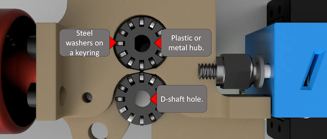
Solution 2 is essentially a remix of a wades type pinch wheel extruder, using an solid carbon fiber filled PEEK(for its high wear and temperature resistance, and low friction properties) pad in place of one of the typical pinch wheels, and with the addition of omni wheels in place of the typical hobbed pinch wheel that grabs the filament. This modification, in combination with a filament chopper, such as the one from the smuff project, enables applying a thrust to a relatively repidly rotating wire or filament, by pinching the wire between the omni wheel and PEEK pad, and rotating the omniwheel with a stepper motor or gear box drive just as in a standard pinch wheel extruder. The big problem with this implementation is that the omnis are under significant load and this increases friction between the rollers and the axle of the rollers, which generates heat and increases rolling resistance against the wires rotation which can break the wire at high rotation rates.  So i got to designing and modeling how the pats would need to go together to test one of these in practice...

 
Ok now that we have an idea of how it can go together, with all the relevant parts, lets actually try building one. naturally the one we actually fabricate ends up quite different from the one we designed, due to limits of materials and fabrication capability, and the realities of tolerance stackups and real world material strengths and stiffness.  This meant that the omni wheel had to be about twice the diameter of the design, and ultimately trying to get two printed omnis at the size needed with the tolerances required (because no one makes omnis this small, its nearly impossible to find omni's smaller than ~35 mm OD) and the cost of having them made by a contract house would be huge, I ended up just designing them based on an existing design on thingiverse which was quite convenient. making use of 1" key rings as axles for the omni rollers and m2 stainless steel washers as rollers.
 

So lets get this thing mounted and tested


Unfortunately, the washers as rollers concept works well for low rotary speeds of the wire, but not well for high speeds. Further development and refinements to the designs of the omniwheels will be required to make them reliable.

So what about temperature and strain control?

   Without reliable material feeding, temperature and strain control can only offer so much. But, none the less, once the problems with material feed have been resolved, it will be necessary to setup some form of closed loop control of the temperature and strain rate of the material being deposited through the rotating die. In the same way it proves necessary to use PID to control the temperature of the hot end in FDM. Since material viscosity in solid phase processing depends strongly on temperature, force and strain rate, and the micro structure of the product depends strongly of on the processing history, it is critical to develop reliable probes for these three parameters that can work in situ, in real time, and with the highest possible accuracy to the actual values encountered in the processed material.

Unfortunately, there are some problems with existing solutions to measuring temperature, force and strain rates in very small rapidly rotating assemblies. Contact thermocouples are generally highly dependent on surface contact state, and have wear life limitations associated with high rotation rates of rotating assemblies like our rotating die. More importantly because the volume of material we are working in Rotoforge is so small, most thermocouples have masses comparable to our worked material and so significantly skew the results of the measurement(think measuring the velocity of a tennis ball by hitting it with another tennis ball). So direct contact methods are out for now...

Non contact methods are really the only practical means we have of extracting temperature data. Among the most common non contact methods, pyrometers, and bolometers (thermal cameras) are first to mind. However, the temperature range capabilities of cheap devices rarely reach above ~450 degrees C, which is too low for the printing temperatures of most metals, and may be a bit close to the margin for aluminum alloys. Further, pyrometers and bolometers require accurate calibration, and few such accurate calibrations exist for a material undergoing solid phase deformation at a high rate in a small volume. There is still little understanding of how surface emissivity may evolve with defect density in metals, IE how severe plastic deformation may skew the temperature measurement; to say nothing of the challenge of measuring the temperature of small spots accurately due to the typical low resolution of most modern thermal sensors (especially for high temperature measurements). Thermal microscope cameras do exist, but are typically relatively bulky and expensive and optics for high magnification of IR radiation are similarly priced.

This situation sounds hopeless until one considers all the properties of a metal which change with temperature substantially enough to be measured, and repeatably enough to be useful. From the first principles, a reason metals being severely plastically deformed are able to bond with their underlying substrates(and with the die they are forced through) and are able to rapidly change shape is due to the liberation of electrons participating in the metallic bonds which hold the solid metal together and make it rigid. When energy is introduced to the metal in the form of heat from friction, or as mechanical shear deformation, these bonding electrons are freed in some numbers in proportion, and this facilitates the breaking of bonds and thus the change in viscosity into the semi-solid regime. 

Fortunately, the liberation of electrons also alters the charge state of the metal atoms in the material, and changes the effective electrical resistivity of the metal (and other metals in contact with the deforming metal whose temperature rises by conduction heating, like our die). While making electrical contacts robust to rapid rotation and high temperatures is difficult, this change of electrical resistivity also makes it more difficult for electrons to form eddy currents in response to a changing magnetic field, as per faradays law of induction. Essentially, if we consider the deforming metal, or a die in contact with it as the core of an inductor, it becomes possible to observe the temperature dependence of the inductance (really of the saturation current in the core) by applying a magnetic field to the "core" with a coil, and then measuring that magnetic field as it "rings down" in the core. Put simply, the current induced by the electromotive force applied by the initial magnetic field of the driving coil, subsequently induces a magnetic field of its own, whose intensity depends on the saturation current that was initially generated in the core by the initial magnetic field, and which itself depends on the electrical resistivity of the "core" at the temperature of interest and the mechanical plastic deformation state.   The following cartoon illustrates somewhat how this drive and response interplay occurs in cross section of the rotating shaft/die and copper inductor coil assembly.

The copper coil generates a magentic field in response to a supplied current from the driver board.

The magnetic field from the coil induces a saturation current in the die and wire and shaft, according to their relative permeabilities. H13 tool steel die is the most permeable by a factor of 50 or more. Thus it contributes primarily to the response.

Drive coil then turns off, and listens for the "response" magnetic field of the saturation current in the die as it rings down from the initial drive coil magnetic field pulse.

The response magnetic field generates a measurable return current in the drive coil, and this return current magnitude can be converted to a temperature value of the die based on either calibration data (provided by shields) or a known temperature dependence of the permeability of the material being measured.

Serendipitously, H13 tool steel (our favored and most wear and gall resistant available die material that is easily workable)  has a curie temperature around 880 degrees C.  (Wikipedia on Curie temperature for the unintiated)This implies that its magnetic response behavior, IE its saturation current has a relatively linear dependence on temperature proportional to its temperature coefficient of electrical resistance which is large enough to be easily measurable with affordable electronics as Andrew has demonstrated with his circuit and coil design and subsequent testing. Additionally, this technique is potentially sensitive to barkhausen noise, if a frequency component of the response magnetic field is measured. This barkhausen noise can be used to measure strain (thus applied force) and deformation, that is, strain rate in the deforming material. 

Above the curie temperature, measurements can still be made but the response is nonlinear and this complicates further measurements. Additionally, the magnitude of the response declines toward zero as the order of the magnetic domains is disrupted at higher temperatures still. So the practical upper limit of temperature measurement depends greatly on the stability of the magnetic response character (the permeability) of the material you are using as the inductor core. 

This particular development (largely with the assistance of Andrew Shields(Shieldsexperiments), Rob Herc, Paul(Parkview), Sam (Sparkgap) and others from our discord channel. is potentially very useful in a wide variety of rotating assembly measurement situations and can be found, schematics, test data and all as well as a brief user manual,on the electronics section of the Rotoforge discord, and github pages as well as at Shield's personal github page.  There may be a wide variety of applications for this technique, in many fields beyond our little project as it bears a resemblance to NMR/MRI and many other techniques. I am extremely grateful for their assistance and consultation in building it according to the needs of the project and solving this problem for me and future developers.

I have included the circuit diagram and initial calibration data (from 30 to about 450 degrees C) for a H13 tool steel die (both courtesy of Andrew shields) in their current entirety for completeness and thorough documentation purposes in the event of future catastrophe here as well. I have also included all the data sets I have collected on the previous friction die extrusion experiments... and the data that this graph for the thermomagnometer was pulled from courtesy of Andrew Shields.


So what else can we do?

In the interim a commercial company released a rather nice CNC mill with a tool changer and auto leveling which appears to be an excellent opportunity to implement serial friction surfacing as a method of metal additive manufacturing on the desktop at somewhat higher cost than I would like but very nearly in reach. One could easily imagine a machine like the makera grabbing individual rods of constantly reloaded sections of feedstock from the tool holding area, and depositing those rods onto a build plate one at a time as in friction surfacing, to form 3D objects. Indeed, I know of one person who has done this with some success already in a startup context. Alas, 5K USD is a bit too rich for my grad student blood. 

So what is next?

So we shall move on...

So, seeing that these approaches were becoming increasingly mechanically complicated and prone to failure as a result, i opted to test a simpler hypothesis based on a system we all know well by now.
FDM.

In the next post I will explain why I have opted to pursue a metal FDM via conduction heater approach after struggling with the friction welding technique for so long.


Sunday, April 23, 2023

Rotoforge 2023-04-24 - Basic Physics of Rotoforge


 Introduction-

    Thus far I have not been totally clear on the specific physics, and set of process models to which we should appeal for guidance in designing and determining the appropriate extrusion settings for Rotoforge... The process parameters are sufficently divergent from those typically used in friction stir welding, and additive friction stir deposition, due to the change in scale and the general opacity of the literature, that I have not found existing literature of the most help.

However, after further research in wire drawing, reading a variety of papers and guides written in the 30s, 50s, 70s, and 90s, and running a few experiments most of which failed, but a few of which resulted in stable extrusion of aluminum 6061-T6 wire, from a 1.6mm OD wire feedstock, without a shaft liner, without a guide tube, and without any special modification to the hollow shafted brushless DC drone motors I have been using, nor any special materials, beyond the stainless steel acorn nut nozzle of yore, I believe I have a reasonable set of theoretical assumptions from basic physical first principals which can guide our choice of printing parameters with some reliability.

In the sections below I will first describe which constitutive physical equations I use to determine appropriate printing conditions, then use them to arrive at a set of acceptable printing parameters for aluminum 6061 for Rotoforge, which I have tested and know to be at least valid for stable extrusion. 

The First Principles-

  1. Formula for axial force in wire drawing:

F = K * σy * (do/di) * (1/tan(α/2))

    Where F is the force required to push the wire through the die, σy is the yield strength of the wire material, do is the outer diameter of the wire, di is the inner diameter of the die, α is the angle of entry, and K is a constant that depends on the frictional coefficient between the wire and the die.

     I have opted for this description because it seems to produce more realistic results than cutting force equations in machining or friction stir welding, and is a relevant description of a system nearly identical to Rotoforge, but without the rotation. I have also found it very difficult to obtain stable extrusion with diameter reductions below about ~30% as per typical wire drawing intuition in the literature.

  1. Formula for power due to friction:

Q = F * V * μ

    Where Q is the power due to friction, F is the force required to push the wire through the die, V is the tangential velocity of the wire at the die entrance, and μ is the coefficient of friction between the wire and the die material. 

    This equation probably ignores the resulting heat from sliding friction of the extruding material moving perpendicular to the axis of rotation through the die, but I suspect, based on the velocity of rotation compared to the extrusion speed, that the friction due to linear sliding friction is negligible... I have also opted, due to the surface area to volume ratio of Rotoforge extrudate and feed stocks, to ignore the heat contribution due to plastic deformation. My reasoning for this, is that the surface area of our system per unit length of material extruded, is more than 5X larger, than the volume. This indicates that the vast majority, ~80% or more, of the total heat evolved in the system is due to surface friction, not bulk plastic deformation.

  1. Formula for temperature rise in a solid due to heating:

ΔT = Q / (ρ * c * A * L)

    Where ΔT is the temperature rise of the wire due to frictional heating, Q is the power due to friction, ρ is the density of the wire material, c is the specific heat of the wire material, A is the cross-sectional area of the wire, and L is the length of wire that passes through the die in one second.

A Working Example-

To calculate the temperature rise in a 1.6 mm OD, 6061-T6 aluminum metal wire, if it is forced through a 1.4 mm internal diameter X 0.5mm long, 316L stainless steel die, with a 60 degree entry angle, which is spinning at 15,000 RPM, at a wire length feed rate of 2 mm / second, we need to determine the amount of heat generated due to friction between the wire and the die. 


Figure 1. Initial conditions of interest, before the wire touches the entrance of the rotating die.

This heat generation can be calculated using the following equation:

Q = (μ * F * v) / (2π * r) * l

where Q is the heat generated per unit length of the wire (in watts/meter), μ is the coefficient of friction between the wire and the die, F is the force required to push the wire through the die (in Newtons), v is the velocity of the wire (in meters/second), and r is the radius of the wire (in meters), l is the length of the wire in contact with the die.

First, let's calculate the force required to push the wire through the die. This can be determined using the following equation:

F = (π/4) * (D^2 - d^2) * L * σ

where D is the outer diameter of the wire, d is the inner diameter of the die, L is the length of wire passing through the die per unit time, and σ is the yield strength of the wire material.

Plugging in the given values, we get:

D = 1.6 mm = 0.0016 m
d = 1.4 mm = 0.0014 m

L = 2 mm/s
σ = 276 MPa (for 6061-T6 aluminum)

F = (π/4) * (0.0016^2 - 0.0014^2) * (0.002 m/s) * 276e6 Pa
= 88.4 N

This is within our extruder's capabilities, so we can be sure that we can start the wire through the die when the system starting cold, at a minimum.

Next, we need to determine the velocity of the wire. Since the die is spinning around the wire at 15,000 RPM, we can use the peripheral velocity at the wire surface, which is given by:

v = ω * r

where ω is the angular velocity of the die (in radians/second) and r is the radius of the die orifice (in meters). Since the wire is entering the die at a semi-cone 60 degree angle, the effective radius of the die can be calculated as:

r_eff = r / sin(60)

where r = 0.0014 m is the radius of the die.

Plugging in the given values, we get:

r_eff = 0.0014 m / sin(60) = 0.0016 m

ω = 2π * 15000 / 60 = 157.08 rad/s

v = 157.08 rad/s * 0.0016 m = 0.51 m/s

Finally, we need to determine the coefficient of friction between the wire and the die. This can vary depending on the materials and lubrication used, but a typical value for dry friction between aluminum and stainless steel is around 0.5.  and where l is the length of wire in contact with the die entrance and interior,
Plugging in all the values into the heat generation equation, we get:

Q = (0.5 * 88.4 N * 0.51 m/s) / ((2π * 0.0008 m) * 0.0005 m)
=
8,969,176 W/m

Figure 2. Heat is generated according the heat generation equation which includes the friction in the die at the applied constant extruder force, the constant RPM, and the  geometric parameters of the die. This "evolved heat" is primarily a result of mass flow at a constant frictional loss, and so scales with feed rate, or with RPM independently, so long as one keep these two values within the tolerable levels for the material being extruded. Similar to the machining envelope of table feed(linear wire feed in our case) and spindle speed(die RPM in our case) in conventional turning of materials on lathes and mills.


To calculate the temperature rise, we need to know the specific heat capacity of aluminum, which is approximately 900 J/kg°C.

Assuming the wire has a density of 2.7 g/cm^3 (the density of 6061-T6 aluminum), we can calculate the mass of the wire passing through the die per unit time as:

m = π * (0.0008 m)^2 * 2.7 g/cm^3 * 1000 cm^3/m^3 * 2 mm/s
= 1.23 g/s

Multiplying the heat generated per unit length by the length of wire passing through the die per unit time and the specific heat capacity of aluminum, we get:

ΔT = Q * t / (m * c)

where t is the time interval over which the heat is generated. Let's assume a conservative value of t = 1E-5 seconds, (10 microseconds) for this calculation, since the temperature will tend to change less on short timescales, and we are only considering a lossless system, so we do not want to allow too much time for temperature rise in a perfectly insulating environment.

Plugging in the values, with the specific heat and mass flows in units compatible with watts, we get:

ΔT = (8,969,176 W/m) * 1E-5s / (0.000123 kg/s * 900 J/kg°C)
= 433°C

 In reality there will be large losses due to thermal conduction through the wire feedstock, the die walls, and convection to the air. I am not really equipped to characterize these losses fully just yet but will return to them in future. 

What It All Means-

Thus, the temperature rise in the 1.6 mm OD, 6061-T6 aluminum wire forced through a 1.4 mm internal diameter, 316L stainless steel die, 0.5mm long, with a 60 degree entry angle, spinning at 15,000 RPM, and at a wire length feed rate of 2 mm / second, at a time of 10 microseconds after contact would be approximately 433 °C .... under lossless conditions.  Below is a real experiment based on the above calculated values, which resulted in very stable continuous extrusion of aluminum 6061 wire through a stianless steel die.

Figure 3. Microscope images of 316 L 1.4 mm ID X 0.5 mm long stainelss steel die, extruding Aluminum 6061-T6 to 1.4mm OD, from a 1.6mm OD wire feedstock. In this test, we obtained stable extrusion until we ran out of wire to feed, with an extrudate surface that was smooth and uniform. This was obtained with no shaft liner, no guide tube, and not external thrust assembly. we observed the smoking of the 10W-40 full synthetic motor oil used to lubricate the interior of the shaft off of the extrudate surface.

Considering the smoking off of the 10W-40 synthetic motor oil on the wire surface, My best guess for our real wire temperature without a direct measurement(complicated by emissivity, and target size) would be a minimum of ~250 °C based on the smoke point of such oils typically.  This temperature is substantially below our estimate, which makes sense under steady state conditions with real world conduction and convection losses. By comparing the real value, as well as we can measure it, with our calculated values, we can start to estimate the magnitude of those losses and, for a given configuration make reasonable accommodation for them in future predictions and thus improve the consistency with which we can hit the target print parameters for stable material extrusion and deposition.

Fortunately, as a result of the physics of wire drawing, the force required to push a wire through a die of smaller diameter does not typically increase with pushing speed, although the heat evolved does increase, and this can change the friction conditions at the die orifice, which can effect the pushing force requirement.

Figure 4. If the system can sustain a doubling the feed rate at a constant extruder force and die rpm, the evolved heat should double as well. Similarly, doubling the RPM at constant feed rate should also double the evolved heat. In the feed rate case, the motor torque and power at the target RPM are the limiting factor, while in the RPM doubling case the friction properties of the die and feedstock are the limiting factor. In the balance of these factors to obtain a target extrudate temperature, IE viscosity, is the ideal condition for Rotoforge printing found.


Basically, extrusion ratio impacts extrusion force, but total material mass flow rate (linear wire feed rate) does not,  while motor torque demand depends on mass flow rate, and this directly influences the evolved heat at the wire surface.  

So 2X the feed rate to 4 mm/s would make the evolved heat roughly double, to ~16,000,000 W/m... this means we can make up for the thermal loss paths by increasing wire feed rate to increase heat evolved at some constant extrusion ratio, and some constant motor torque capacity(power output) at the target die RPM, which can be selected based on the literature machining parameters of the wire feedstock material. The E3D Hemera, our current extruder is capable of maximum feed rates of ~250 mm/second, principally.  This would represent a truly enormous evolved heat...

But What About Actually Printing?-

Since we now have a first principles understanding of and some reasonable models for estimating printing parameters, how do we pick a target that allows us to not just stably extrude, but to deposit material onto a surface on onto itself, IE, PRINTING! 

All materials have a temperature dependent yield strength. Al-6061 is no exception to this rule, as seen below in figure 

Figure 5. the temperature dependent yield strength of Al-6061 and other alloys.

 Since we can now target extrudate temperatures with some precision by controlling wire feed rate, motor RPM, and layer height, we should be able to adjust the extrudate temperature to some temperature(say between 350-500°C) where the material extruding from the die, will deform into the all too familiar flash, on the build surface / previously deposited layer, and form a deposit on the underlying surface.  Except, instead of the flash galling against the inside of the motor shaft and jamming things, it will expand, and rub against the outside of the die, which will flatten and stir it onto the underlying surface. 

Figure 6. A cross section of what the formation of a flash and a deposit might look like, as well as cartoon representation of secondary heat sources from friction between die and extrudate flash which should form under the constant extrusion force, once an appropriately high extrudate temperature is obtained to facilitate viscoplastic flow of the extrudate under the applied extruder force.


figure7. one can imagine this situation, but occurring just outside the tip of the die and the deposit as shown, being constrained between the outside of the die and the build surface.

 Rather fortunately, the die reducing the diameter of the feedstock as it extrudes should help to concentrate the extruder force on a small area of hot extrudate, which will increase the effective compressive stress on the extrudate and hopefully make generating a deposit easier....

All that remains is to start trying to deposit the aluminum onto a build surface, and adjust our feeds and speeds until we can obtain sufficient extrudate temperature to produce reliable deposition.


Wednesday, March 22, 2023

Rotoforge 3/21/2023

    In my last update I mentioned that we "solved a problem" with the welding of the metal feed stock wire to the walls of the rotating BLDC shaft. This turned out to be a better, but not wholly effective solution. In time the glass fibers in the liner break down and create alumino-silicate dust due to heat and abrasion against the hollow shaft walls, and the wire feed stock itself, particularly the foot that forms when the wire presses against the rotating die/nozzle. 

Figure 1. A closeup of the business end of Rotoforge with the die/nozzle removed. This reveals the foot, AKA "flash" that has formed where the wire contacts the rotating die, as well as a protrusion where the material was previously extruding at the bottom of the image. The damaged state of the glass fiber liner is also apparent.

The glass fiber liner is relatively effective at preventing contact between the wire and the rotating shaft wall, particularly when the liner is impregnated with 10W-40 motor oil. However, because the liner is not rigid it does not effectively constrain the growth of the "foot" or "flash" as it is sometimes referred to in the literature. Basically:

  1. When a material contacts a rotating surface heat is generated from friction. 
  2. This heat softens the materials.  
  3. At some temperature the material strength will decrease(the material will soften enough) to a point that the material begins to flow like a fluid. 
  4. Once the material begins to flow, fluid mechanics demands that it must flow through the path of least resistance.
  5. Conservation of mass demands that the material that flows through the path of least resistance must be replaced by other material that has been softened sufficiently to flow as well.

In Rotoforge, because the motor shaft is of a larger diameter than the wire, there exists space for material that has been softened to the flow-able state to extrude into the space between the wire and the shaft. This reduces the flow rate through the nozzle/die, and causes problems with destroying the glass fiber liner, and eventually with welding/galling to the walls of the rotating shaft which jams the motor. This is similar to the unconstrained flash growth that occurs in the literature and is described broadly as being the result of extrusion of plasticized material under load. as in figure 2.

Figure 2. a helpful diagram from Vilaca et. al showing the formation of a viscoplastic region in a piece of rod being friction surfaced onto a plat, and subsequent extrusion of flash from the contact region when the material is unconstrained under load and heat form friction.

There are several ways to approach this problem. 

  1. Increase the wire diameter to reduce the space for the flash to form
  2. Reduce the shaft internal diameter by making a custom shaft
  3. Inserting a tightly sealed stationary guide tube through the shaft which presses against the rotating die and prevents the wire from contacting shaft walls, and constrains the flash/foot.

The first method is somewhat impractical due to the undesirable scale up of cross sectional area of the wire, and scale down of the extrusion pressure at a constant force as a result.  Perhaps a more powerful extruder with better grip, like the proper extruder. To obtain the required tolerances between wire and existing stock shaft, we would need a wire with OD of ~2.2mm which gives a cross sectional area of ~3.8 square millimeters. Even with the best off the shelf bowden sytem, no more than 100 newtons of force is available. This principally provides enough pressure for extrusion, but only under ideal conditions. In reality, force will be spread out over the whole area of contact between the wire and shaft. 

 A tight fit with the shaft and wire in the current configuration also poses a galling/welding problem, as 1045 carbon steel(the shaft material) is readily wet by hot aluminum, zing and other metals, and thus, is likely to seize under the high RPM and temperature conditions in the Rotoforge printhead. 

 The second option will require acquiring a lathe and doing substantial custom design work. I will say no more about it for the time being.

The third option is what I decided to attempt recently to overcome the reliability problems with the glass fiber liner and various lubricants.  This required the removal of the retaining screw for the motor bell to fit the stationary guide tube, and thus the supporting of the motor bell with an external thrust bearing structure.  The insertion and support of the guide tube itself was also somewhat tricky.  some images of the guide tube assembly and the whole print head assembly with external thrust bearing are provided in figures 3 and 4. 

Figure 3. The pneumatic bowden fitting with guide tube installed. The guide tube is made from 13 gauge luer lock needles from mcmaster. The needle's luer lock head is cut short, leaving just a small collar to retain the assembly inside the pneumatic fitting. This collar is soldered in place to the inside of the pneumatic fitting. 

The luer lock-pneumatic bowden fitting assembly screws into the gantry mount plate and holds the needle floating in the middle of the rotating hollow shaft.Figure 4 shows the complete assembly with external thrust structure...

Figure 4. The complete rotoforge printhead assembly with external thrust bearing structure and stationary guide tube inserted. the thrust structure is an off the shelf Z bracket from mcmaster along with standard bearings and mounting hardware.

It was important to make sure the length of the guide tube allowed it to press tightly against the inside of the die/nozzle (acorn nut) to form a seal. This tight sliding contact fit also necessitated more careful concentric drilling of the acorn nut die/nozzle, due to the unfavorable interaction (cutting/shearing) that the die orifice had on the guide tube end in operation.  The setup for which I show in figure 5. In short, I took advantage of the low run out and high RPM capability of the BLDC motors to drill highly concentric die holes on my mini mill...This technique has been elucidated previously in the course of the reprap project and elsewhere as general machinists knowledge. The BLDC spins the part to be drilled, while the bit is held stationary like on a lathe. Slow well lubricated drilling with the aid of a bubble level for part leveling enables highly straight concentric holes to be drilled in the die/nozzle. The CNC mill here is a genmitsu pro 3020.

Figure 5. setup for using the BLDC motor and a mill as a highly concentric support and drilling tool for making straight concentric die/nozzle without a lathe.

Unfortunately, even this stationary rigid guide tube approach failed due to flash formation and galling. Essentially, what appeared to happen was that the flash/foot would form inside the stationary guide tube at the entrance to the die, material would begin to extrude through the die, and then some amount of play in the external thrust structure would open up the gap between the die and the guide tube allowing more material to flow into the seal, and eventually this material would cool and gall against the stainless steel guide tube. Occasionally breaking off pieces of the guide tube end or the flash from the feed material ultimately halting material feed due forming a plug of metal galled inside the guide tube.  Figure 6 shows an example of a flash that caused an extruder jam.


Figure 6. the end of the hollow shaft with the die removed, showing a galled plug of aluminum metal filling the end of the guide tube, resulting in an extruder jam.

Figure 7 shows what the situation looked like once I cleared the jam by pulling the guide tube out and tugging on the wire with a pair of pliers to break the galled material loose.

Figure 7. flash has been galled off by contact with the stainless steel guide tube end. The guide tube has been retracted to free to motor, and this is what remained after the tube was broken free.

Given this latest reliability failure I have opted to go the custom shaft route. My kind, caring and ever supportive partner, Sam, has provided me a lovely Proxxon FD150E micro lathe to do the work with as a birthday present. 💖

Fortunately there is some preexisting reasoning for making custom nozzles/dies for elevated temperature handling and resisting wetting/galling of semisolid or molten aluminum and other metals. Chris from the hackaday aluminum FDM printer project was inordinately helpful in providing advice on where to source molybdenum alloys he used for the project.  Thus, from his advice and further research on the matter a new plan for the next couple of weeks (once the lathe arrives) has emerged...

1.) Acquire 1/4" Titanium-zirconium-molybdenum alloy rods from mcmaster. or TZM, which are ~96-98% molybdenum. I intend to turn these down on a lathe into replacement shafts for the BLDC motors to solve several problems at once.
TZM is used in hot work tooling for die forging, extrusion, molten metal handling, and injection molding, it is not soluble in molten metals, is resistant to wetting by them at elevated temperatures, and is relatively self lubricating and resists galling similarly to bronzes but at 2X-3X higher temperatures and applied loads and some information about its wide variety of useful properties can be found here.


2.) By custom making the molybdenum into press fit shafts for the BLDC  we can also eliminate the clunky external thrust bearing and replace it with a simple flange on the molybdenum shaft end.  this saves weight, and reduces rotating assembly losses due to friction in additional bearings and mechanical contacts...My experience with the external thrust bearing has mostly been an unstable and lossy one due to all the additional mechanical interfaces.

3.)We can also control the exact tolerances of the interior of the shaft, and thus how closely it conforms to the wire feed stock. This is important, because it is necessary to have a tight fit, with low friction between the wire and the shaft interior to facilitate a stable lubricant film (as in a fluid bearing) and to restrict back flow of plasticized material at the die orifice in the form of flash.  Additionally, having the die orifice be integral to the shaft, IE machined into it, instead of threaded on as with the acorn nuts, should eliminate problems due to play in the threads under high extrusion loads, and with the die unthreading during use. In general, a machined part saves mass, provides better tolerancing and durability and eliminates mechanical slop in the system which should help us better control the flow of plasticized material at the die/nozzle orifice.


Thus has been the basic course of experiments in the last few weeks... interspersed with a visit to the lunar and planetary sciences conference in Houston Texas.  Met plenty of fascinating new people, scientists and engineers alike there, many of who may have some valuable insights in the future. 

Such is the plan for the next few weeks of experiments. 

If you made it this far, thanks for reading and look forward to some additional youtube updates and blog post updates soon where I will be making this custom molybdenum die/nozzle/motor shaft! 

I have been hemming and hawing on whether I should ask for support from my readers / community for these projects... they get rather expensive and take a great deal of time. I am not yet comfortable asking for people to support the project without concrete an reliable printing though. 

I suppose you all could tell me in the comments below. I would love to know how you feel about it and if you think this project is worth investing in. 


Monday, February 13, 2023

Rotoforge 2/13/2023

Today we solved two major problems at once... 

1.) We finally managed to find a liner material that survives during extrusion and is extremely effective at preventing welding between the wire feed stock and the motor shaft walls. This welding was previously responsible for nonrecoverable jamming and welding of multiple motors...

 2.) We finally managed to eliminate "candy caning" as seen in the figure below, completely. That is the shear coupling between the wire feed stock and the rotating die has been eliminated without eliminating the energy transfer between the tip of the wire and the inside surface of the die that facilitates frictional heating and extrusion of the wire onto the build plate. this was previously responsible for breaking the feedstock off inside the shaft and causing jams... In short, lubrication and higher RPM helped with this point.

Figure 1.) showing the candy caning of previous iterations of rotoforge wire feed stock... the twisting force imparted due to the force of friction at lower RPM and higher feedstock pressure causes greater shear coupling between the fluidized metal in the die and the rest of the feedstock, this causes twisting and often breakage which results in a jam.

As it turns out conventional motor oil, particularly heavier grades such as 10W-40 and 15W-40 full synthetic contain pressure and shear sensitive additives for reducing wear and oil film disruption such as ZDDP. These additives in tandem with a robust, heat and abrasion resistant mechanical barrier, such as E-glass fiber, provides for an excellent high speed, high temperature tolerant bearing between the metal wire feedstock and the walls of the rotating shaft. This next section includes some points of theory, and may be a little techy so I will try to provide some explanatory graphics and easily referenceable sources for guidance.

 1.) this paper, and a few others provide information on the requirements to print aluminum in the solid state. Their stated operating parameters were:

  • 1000 RPM
  • Ram force (extruder pressure) = 10 -21 MPa
  • layer thickness of 1 millimeter
  • track width of 20 millimeters
  • D_f = Feed rod diameter of 15.9 millimeters, A_f, cross sectional area of  198.56 square millimeters
  • A_n =Die orifice (nozzle exit area) 70 square millimeters
  • Die orifice length of ~10 mm
  • the extrusion ratio, or the ratio of nozzle exit area to feed rod cross sectional area is ~2.84
  • This indicates a nozzle exit diameters of ~9.4 millimeters
  • A surface area to volume ratio at their die orifice of ~2.42
  • A characteristic working volume of  >= 582.56 cubic millimeters

    In our present iteration of Rotoforge, our accessible printing parameters are thus
  •  29,000 RPM
  • Ram force (extruder pressure) = 7-15 MPa
  • layer thickness of ~0.1 millimeters
  • track width of ~ 2 millimeters
  • D_f = feed rod diameter of ~1.6 millimeters, A_f, cross sectional area of 2.01 square millimeters
  • A_n = Die orifice(nozzle exit area) of 0.717 square millimeters
  • Die orifice length of ~1 mm
  • for the same extrusion ratio as above, this corresponds to a nozzle exit diameter of 0.95 millimeters
  • Our resulting surface area to volume ratio would be ~6.17
  • a characteristic working volume 5.727 cubic millimeters

Before we consider anything more complicated, such as the specific behavior of dry or lubricated metal on metal friction at low sliding speeds (1-20 m/s), a few important features stand out from comparison of their parameters to ours. 

  • 6.17 : 2.42 ratio of surface area to volume ratio implies a ~ 2.5 X larger loss path for heat conduction away from the volume of worked material in the die orifice, on the build plate and inside the feed stock above the die for Rotoforge... this is a point against us in terms of ease of flowing material due to the greater loss of heat generated by friction between the feedstock and the rotating die, but a point for us in terms of die longevity and system thermal control. this also implies that our system could sustain higher proportional mass flow rates while staying in the thermal envelope of the materials used in the die, and other components.

  • 582.56 : 5.727 cubic millimeters volume ratio implies ~100X smaller heat generation due to volume plastic deformation in Rotoforge versus large scale commercial systems.  This again is a point against us in terms of material being flowable, since the total heat evolved is smaller, the feedstock material will generally remain at a lower temperature for a given amount of input energy from friction between the feedstock and the rotating die. this is largely negated by the fact that the total volume, and thus mass of feedstock to heat is also smaller by the same 100X factor.   This bodes well for thermal management as it reduces the total waste heat that must be dissipated from the system to maintain the same proportional mass flow rate of feedstock through the die.

  • With nothing but a guess at the length of the die orifice in the paper above, I cannot say for sure what our proportionate die orifice length should be, but I can guess that shorter is better to within the limits of the hot strength of the die materials as it reduces friction between die walls and extrudate and reduces total extruder pressure required to obtain a given mass flow rate.

  •  Ram force is in the same ball park... Rotoforge could probably do with a better extruder that is less prone to slippage and provides at least 25 MPa of pressure, or about 25 newtons / square millimeter... or for a 1.6mm diameter feed stock, an extruder capable of ~50-100 netwtons total force on the feedstock metal wire.
     
  • Without reference to non-extant exact theory, but with some papers for your perusal if you care for more details..  in general, the force of friction decreases with speed in soft metal - hard metal contacts. In effect, high shear rates and elevated temperatures due to friction, in the absence of welding, produce a situation like a metallic fluid bearing. This very imprecisely means that for our system specifically, between aluminum and stainless steel, the force of friction should decrease linearly with RPM, thus reducing the net shear strain on the wire feed stock away from the die-feed stock interface.
  •  Simultaneously, the energy released due to this sliding fluidized metal friction between metallic surfaces, scales as the surface velocity squared. given that our die orifice is ~2.7 mm in circumference, and is rotating at ~29,000 RPM, our effective surface speed at the orifice edge is 78,300 millimeters / minute, or approximately ~1.305 meters/second. The surface speed of the large commercial system at the die orifice is ~28,200 millimeters/minute, or approximately, ~0.433 meters/second. this means, comparatively, that our "frictional energy" is about 9X larger, per unit feed stock surface area,(due to 3X the surface velocity and the velocity square in the energy term) at the interface between our wire and die, than their rod and die assuming the same applied extruder pressure and assuming the same coefficient of friction (this is almost certainly false, but within an order of magnitude).   This means we should be in the ball park, in spite of the larger thermal loss paths and smaller volume, all other things equal, to print aluminum 6061-T6 with our current Rotoforge setup.
  • If we move to a more powerful and faster spinning off the shelf motor or belted offset spindle drive, at 60,000 RPM, we could obtain surface speeds at the orifice of ~2.8 meters / second, or about ~36X the surface friction energy of the large commercial system.  TLDR; more speed is better when it does not adversely effect longevity. cost or safety.  More input energy at the feed stock - die interface results in a lower feedstock viscosity, and a larger mass flow rate through the orifice for a constant extruder pressure.  

    So you might be wondering as I have, what is the holdup!?
    The answer seems relatively simple : Material confinement! 
In short, because the end of the wire is under pressure, at elevated temperature and shear rates, and is thus behaving as a fluid, it flows to fill the space available to it! 
Figure 2). You can see the expansion of the 1.6 mm diameter Al6061 feedstock to 2.2mm diameter foot, where it contacts the interior of the rotating die. 2.2mm is the internal diameter of the hollow motor shaft to which the die is tightly attached. The feed stock has expanded to fill the diameter of the hollow shaft, because it is unconstrained radially and so, once fluidized under pressure, flows through the path of least resistance(outward toward the walls with the centripetal force) until it fills its container.

This expansion of the end of the wire results in an increase in diameter to ~2.2-2.4 millimeters. This results in an increase of surface area to nearly ~4 square millimeters, thus cutting the pressure applied by our extruder at least in half.  Hence why the material can begin to flow, and then stop flowing once the pressure is reduced due to the larger area of contact.

Figure 3.) Initially the feedstock is a simple cylinder with a diameter of 1.6 mm and a surface area at the tip of ~2.01 mm squared. There are two flow paths available given the finite extruder pressure... once the feedstock is heated by friction and begins to flow, the extruder pressure and centripetal force cause it to flow into the open flow paths.

Given our limited pushing power, 14-30 netwons at most, dividing that force over twice the area easily brings us from ~7-15 megapascals of pressure to ~2-7 megapascals. Which is below the threshold flow stress for Aluminum 6061 at it's solidus of 595 celcius, and below the extrusion pressure used in the above paper, by a factor of at worst, 10X, and at best 1.5X ... we may have 9X the input energy per surface area of feed stock, but if that energy is spread over 2X as much area, and we lose 2.5 X as much energy to thermal dissipation, we would already be behind in terms of the viscosity of our feedstock(in response to the decreased energy density) at the die opening, despite this increased surface friction energy working for us.


Figure 4.) Once the feedstock has begun to flow into the die orifice and has filled the initially open flow paths, the extruder pressure decreases, as the force the extruder can apply is constant, but the bearing area of the end o the wire has increased in proportion to the square of its change in radius. now 2.2 mm in diameter, its effective surface area is ~4 square mm. This cuts the extruder pressure at least by half. Additionally, contact with the walls further increases this bearing area over which the extruder force is spread, thus further decreasing the pressure. To make this worse, the extrudate has its own bearing area to contribute, and a relatively large surface area on which friction in the die orifice can act. This increases the reaction forces substantially. Thus extrusion stops.

 Our next order of business will be producing a new die shape, that constrains the feed stock and prevents this expansion at the interface as much as possible, in order to force extrusion through the die opening preferentially without substantially increasing the area of contact. Additionally, an extruder upgrade is certainly in the cards.  A new offset spindle design capable of at least a sustained ~60,000 RPM  is probably a near term improvement as well. 


Figure 5.) The new Rotoforge tool design which will hopefully confine the fluidized metal to the interior of the die, and maintain a constant bearing area, so that the extrusion pressure can remain constant at constant extruder force, and the feedstock material can be continuously extruded.  Ideally the tip catch will hold a tight fit to the end of the wire, without introducing too much additional fricton, and when the wire expands and fluidizes at the tip, it will be captured in the catch and the material will have nowhere to go but through the orifice.

 Thanks for taking the time to read this far if you have! Looking forward to posting some real results in the next month!

Back to the lab!


Rotoforge 2023-11-30 Cold Working and Other Problems

 7 months of implementations later... I thought I grasped the physics. I was wrong. well not completely, but at least 50% wrong, which might...